The Reflection tab is part of the V-Ray Material parameters.
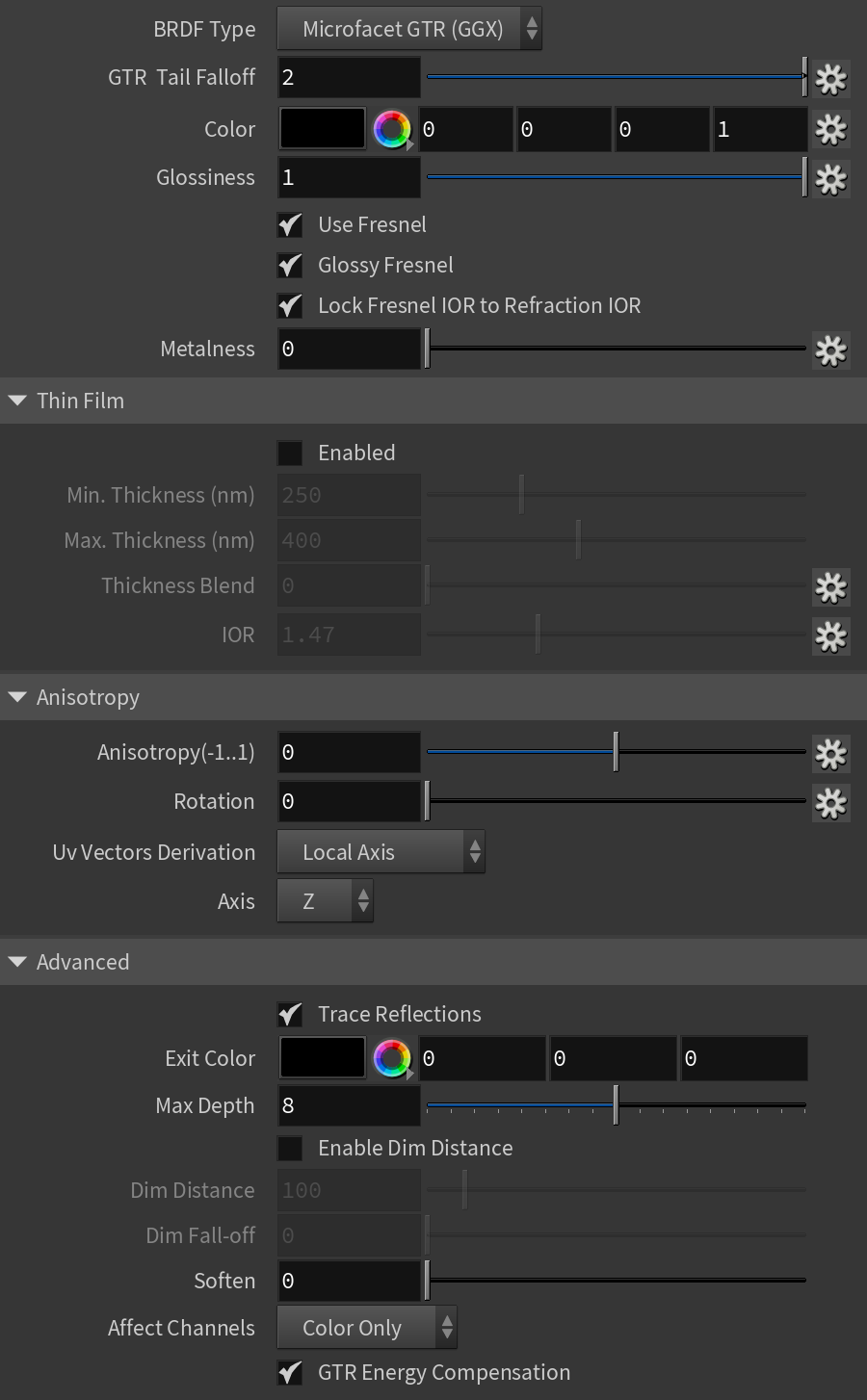
Parameters
BRDF Type – Determines the type of BRDF (the shape of the highlight and glossy reflections). This parameter has an effect only if the Reflection Color is different from black and Reflection Glossiness is different from 1.0. For more information, see the BRDF Type example below.
Phong – Phong highlight/reflections. Specular highlights have a bright center with no falloff.
Blinn – Blinn highlight/reflections. Specular highlights have a bright center with a tight falloff.
Ward – Ward highlight/reflections. Specular highlights have a bright center with a falloff broader than Blinn, but tighter than Microfacet GTR (GGX).
GGX – GGX Microfacet highlight/reflections. Specular highlights have a bright center with a longer falloff.
GGX is the most modern and flexible BRDF (Bidirectional reflectance distribution function) type and is able to better represent a broad range of materials thanks to its ability to control the shape of the specular lobe.
There currently isn't any particular performance difference between models and there is little reason to choose any of the other types.
GGX Tail Falloff – Controls the transition from highlighted areas to non-highlighted areas when the BRDF Type is set to GGX.
Color – Reflection color. Note that the reflection color dims the Diffuse Color. For more information, see the Reflection Color example below.
Glossiness – Controls the sharpness of reflections. A value of 1.0 means perfect mirror-like reflection; lower values produce blurry or glossy reflections. For more information, see the Reflection Glossiness example below.
Use Fresnel – Makes the reflection strength dependent on the viewing angle of the surface. Some materials in nature (glass, etc.) reflect light in this manner. Note that the Fresnel effect depends on the index of refraction (IOR) as well. For more information, see the Use Fresnel example below.
Glossy Fresnel – Uses glossy Fresnel to interpolate glossy reflections and refractions. It takes the Fresnel equation into account for each "microfacet" of the glossy reflections, rather than just the angle between the viewing ray and the surface normal. The most apparent effect is less brightening of the grazing edges as the glossiness is decreased. With the regular Fresnel, objects with low glossiness may appear to be unnaturally bright and "glowing" at the edges. The Glossy Fresnel calculations make this effect more natural.
Lock Fresnel IOR to Refraction IOR – Unlocks the Fresnel IOR parameter for finer control over the reflections. When the Lock Fresnel IOR to Refraction IOR is enabled, the Fresnel IOR is locked to the Refraction IOR.
Fresnel IOR – The IOR to use when calculating Fresnel reflections. Normally this is locked to the Refraction IOR parameter, but you can unlock it for finer control. Note that this parameter has no effect on metallic materials with Metalness value of 1.0 and no metallic map assigned. For more information, see the Use Fresnel example below.
Metalness – Controls the reflection model of the material from dielectric (metalness 0.0) to metallic (metalness 1.0). Note that intermediate values between 0.0 and 1.0 do not correspond to any physical material. This parameter can be used with PBR setups coming from other applications. The reflection color should typically be set to white for real world materials.
Thin Film
Enabled – Turns on/off the thin film effect.
Min. Thickness (nm) – Determines the minimum thickness of the thin film in nanometers. For more information, see the Thin Film Thickness example below.
Max. Thickness (nm) – Determines the maximum thickness of the thin film in nanometers. A map can be used to blend between the Min and Max Thickness parameters, and is expected to be in the range of 0-1. If there is no texture map, only the Min thickness value is used.
Thickness Blend – A map used to blend between the Min and Max Thickness parameters. It is expected to be in the range of 0-1.
IOR – Specifies the reflective index of the thin film. A map can be attached to this slot. For more information, see the Thin Film IOR example below.
Anisotropy
Anisotropy – Determines the shape of the highlight. A value of 0.0 means isotropic highlights. Negative and positive values simulate "brushed" surfaces. For more information, see the Anisotropy example below.
Rotation – Determines the orientation of the anisotropic effect in a float value between 0 and 1 (where 0 is 0 degrees and 1 is 360 degrees). For more information, see the Anisotropy Rotation example below.
Uv Vectors Derivation – Specifies the method for deriving anisotropy axes:
Local Axis – Uses a local axis for the anisotropy effect.
UVW Generator – Allows you to assign a UVW Generator for the anisotropy effect.
Axis – Specifies a local object axis for the anisotropy effect when Uv Vectors Derivation is set to Local Axis.
Advanced
Trace Reflections – Enables reflections for the material.
Exit Color – If a ray has reached its maximum reflection depth, this color is returned without tracing the ray further.
Max Depth – The number of times a ray can be reflected. Scenes with lots of reflective and refractive surfaces may require higher values to look correct.
Enable Dim Distance – Enables the Dim Distance parameter which allows you to stop tracing reflection rays after a certain distance.
Dim Distance – Specifies a distance after which the reflection rays are not traced.
Dim Fall-off – A fall off radius for the dim distance.
Soften – Softens the edge of the BRDF at light/shadow transitions
Affect Channels – Allows you to specify which channels are going to be affected by the reflectivity of the material.
Color Only – The reflectivity affects only the RGB channel of the final render.
Color+Alpha – Causes the material to transmit the alpha of the reflected objects, instead of displaying an opaque alpha.
All Channels – All channels and render elements are affected by the reflectivity of the material.
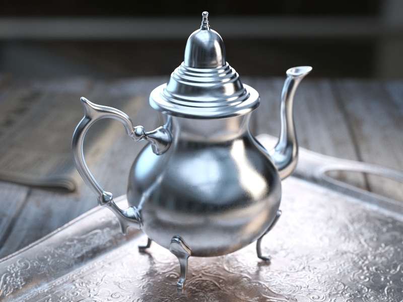
Example: BRDF Type
This example demonstrates the differences between the BRDFs available in V-Ray for Houdini.
Note that the different BRDFs produce different highlights.
The Reflection Glossiness is set to 0.8.

BRDF type is GGX
Modern versatile BRDF type suitable for all kinds of materials.

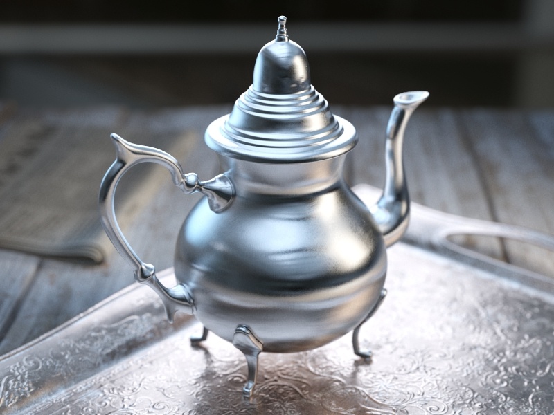
BRDF type is Phong
Best used for plastic surfaces.

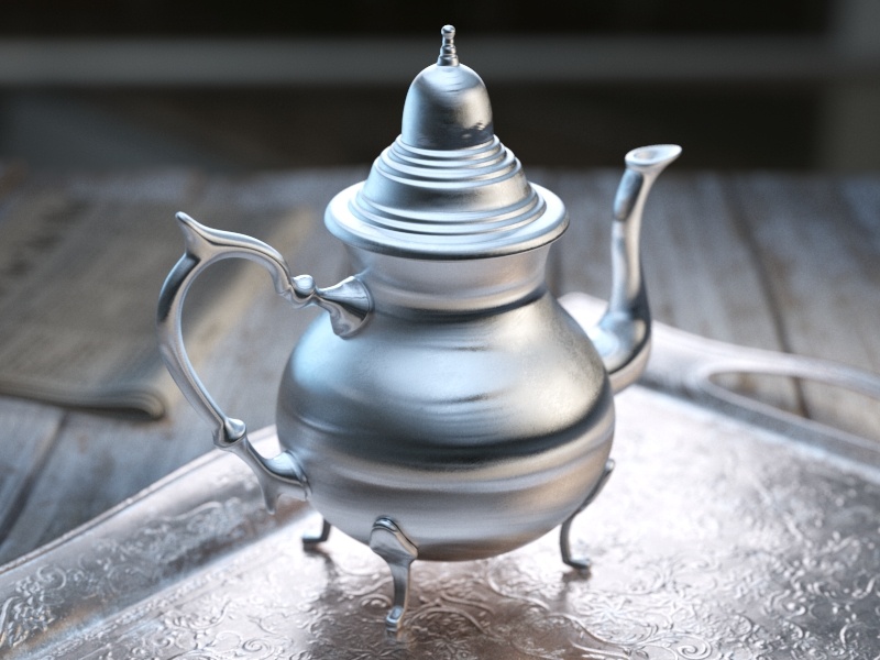
BRDF type is Blinn
Multi-purpose BDRF suitable for many common materials.

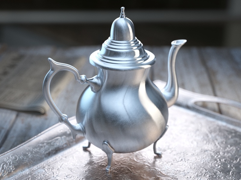
BRDF type is Ward
Useful for cloth materials and chalk-like surfaces.
Slide to change BRDF type.
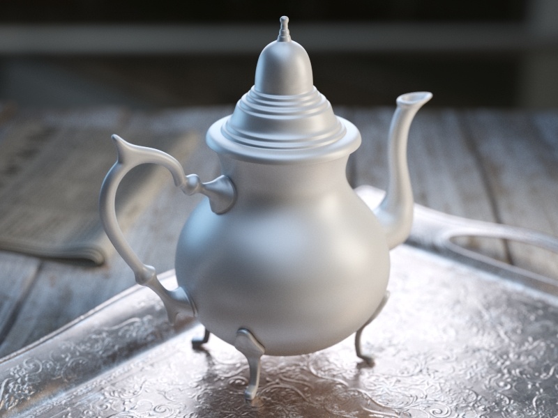
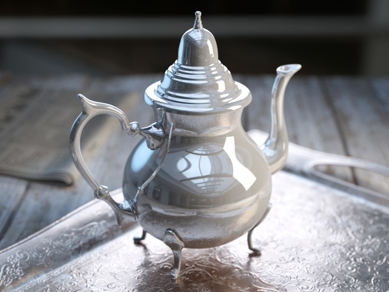
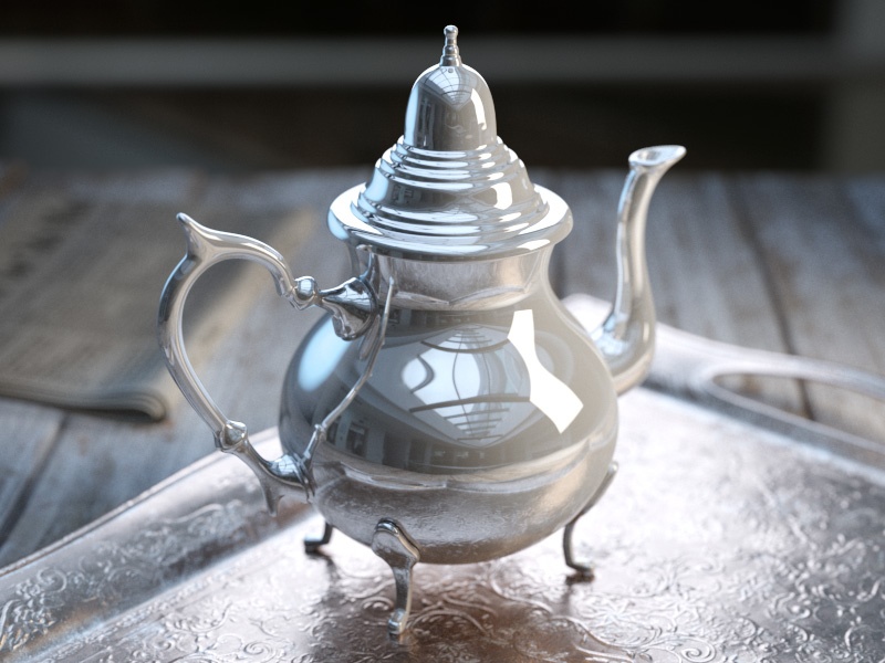
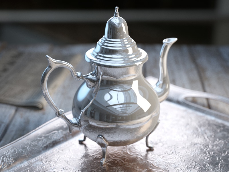
Example: Reflection Color
This example shows how the Reflection color controls the reflectivity of the material.
This color also acts as a filter for the diffuse color (e.g. stronger reflections dim the diffuse component).
Use Fresnel is disabled.

Reflection color is black (0, 0, 0)

Reflection color is (51, 51, 51)
Reflection color is (102, 102, 102)

Reflection color is (153, 153, 153)

Reflection color is (204, 204, 204)
Reflection color is white (255, 255, 255)
Move the slider to see the example renders.
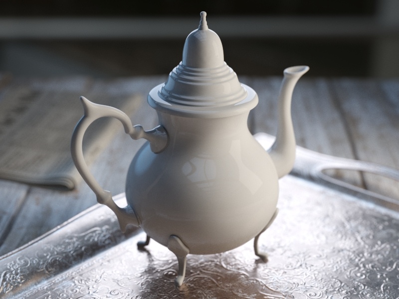
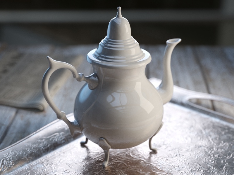
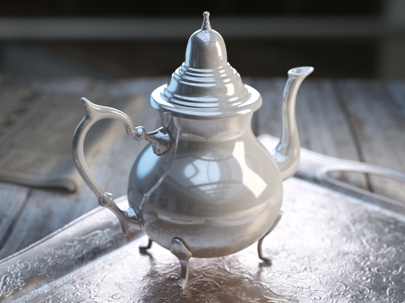
Example: Reflection Glossiness
This example demonstrates how the Reflection glossiness parameter controls the highlights and reflection blurriness of the material. The Reflection Color is white and Use Fresnel is enabled.

Reflection Glossiness is 1.0 (perfect mirror reflections)
Reflection Glossiness = 0.9

Reflection Glossiness = 0.8

Reflection Glossiness = 0.7
Reflection Glossiness = 0.6

Reflection Glossiness = 0.5

Reflection Glossiness = 0.4

Reflection Glossiness = 0.3

Reflection Glossiness = 0.2

Reflection Glossiness = 0.1

Reflection Glossiness = 0.0
Move the slider to see the example renders.
Example: Use Fresnel
This example demonstrates the effect of the Use Fresnel option. Note how the strength of the reflection varies with the IOR of the material. For this example, the Reflection color is pure white (255, 255, 255).

Fresnel is on, IOR is 1.6

Fresnel is on, IOR is 2.2

Fresnel is on, IOR is 2.8

Fresnel is on, IOR is 3.4

Fresnel is on, IOR is 4.0
Fresnel is on, IOR is 4.6

Fresnel is on, IOR is 5.2
Fresnel is on, IOR is 5.8

Fresnel is on, IOR is 6.4

Fresnel is on, IOR is 7.0
Fresnel is on, IOR is 7.6
Move the slider to see the example renders.
Example: Anisotropy and Rotation
This example demonstrates the effect of the Anisotropy and Rotation parameters, which determines the shape of the highlight. For the examples below the Type was set to Microfacet GTR (GGX).

Anisotropy = -0.8

Anisotropy = -0.6

Anisotropy = -0.4
Anisotropy = -0.2

Anisotropy = 0.0

Anisotropy = 0.2

Anisotropy = 0.4
Anisotropy = 0.6

Anisotropy = 0.8
Move the slider to see the example renders.
Rotation = 0

Rotation = 18

Rotation = 36

Rotation = 54

Rotation = 72

Rotation = 90
Rotation = 108

Rotation = 126

Rotation = 144

Rotation = 162

Rotation = 180
Move the slider to see the example renders.
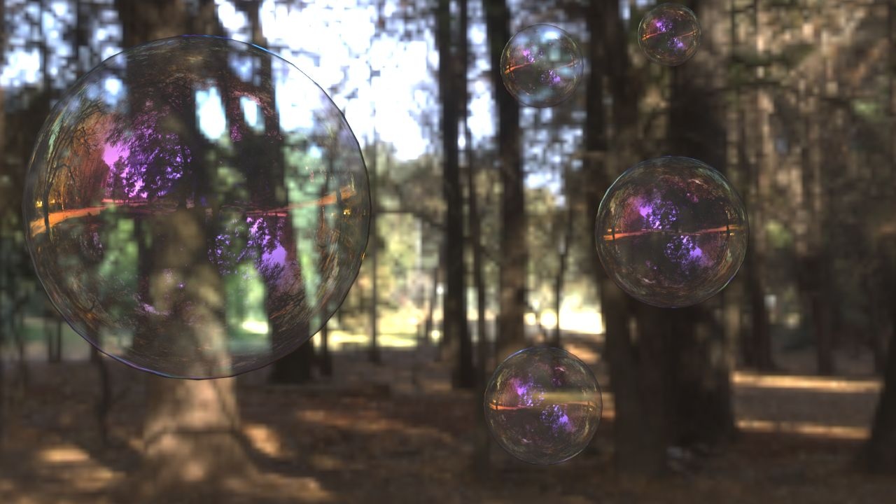
Example: Thin Film Thickness
This example shows how the Min Thickness parameter affects the V-Ray Material. The Thin Film IOR is set to 1.4.

Min Thickness = 0
Min Thickness = 300

Min Thickness = 450

Min Thickness = 600
Move the slider to see the example renders.
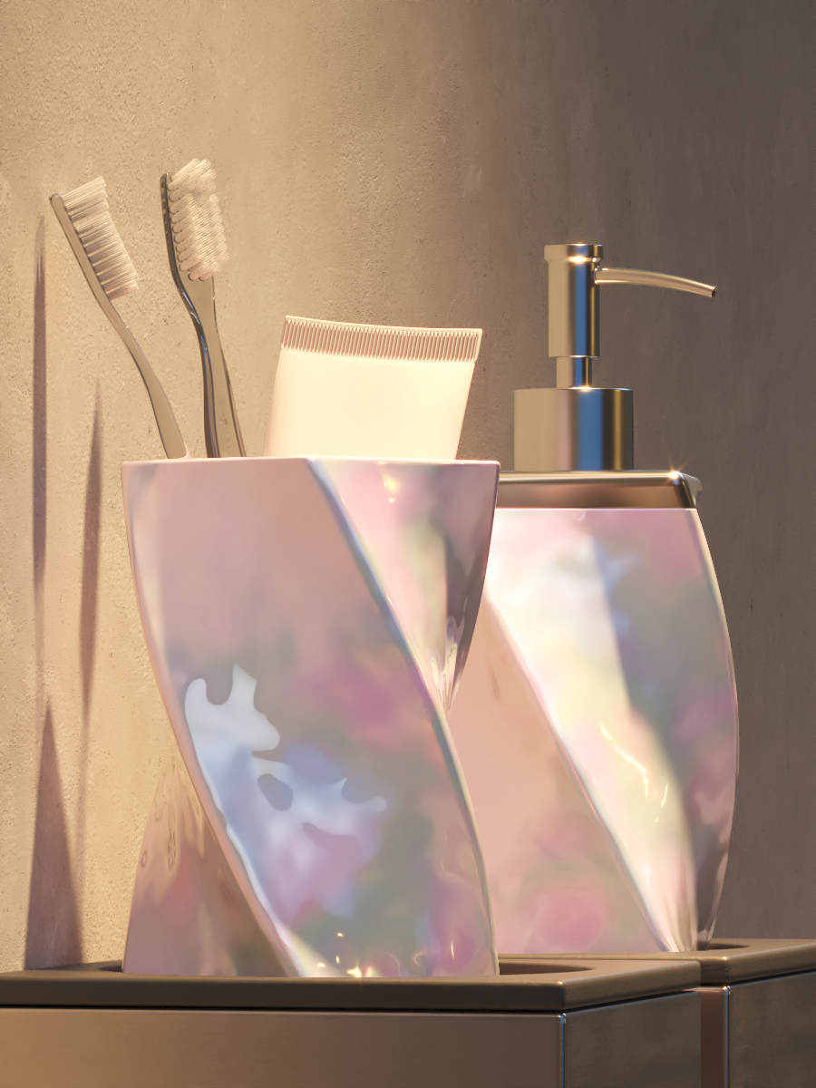
Example: Thin Film IOR
This example shows how the thin film IOR parameter affects the V-Ray Material.

IOR = 2.0

IOR = 2.1

IOR = 2.2

IOR = 2.3

IOR = 2.4
IOR = 2.5

IOR = 2.6

IOR = 2.7

IOR = 2.8

IOR = 2.9

IOR = 3.0
Move the slider to see the example renders.